COVID SAO
PROLOGUE
This is a commemorative item and fund raiser for funds to help battle the many aspect of COVID-19 and just all things 2020. The code has hidden messages of importance that is displayed in the Shitty Ad On (SAO). Below are the assembally instructions for this project.
Let’s get started!
Material Needed/Suggested:
Soldering Iron - Chisel Tip
Solder - (60/40)
Solder Flux - (No clean flux)
Tweezers
Tape
Circuit board holder
Voltmeter
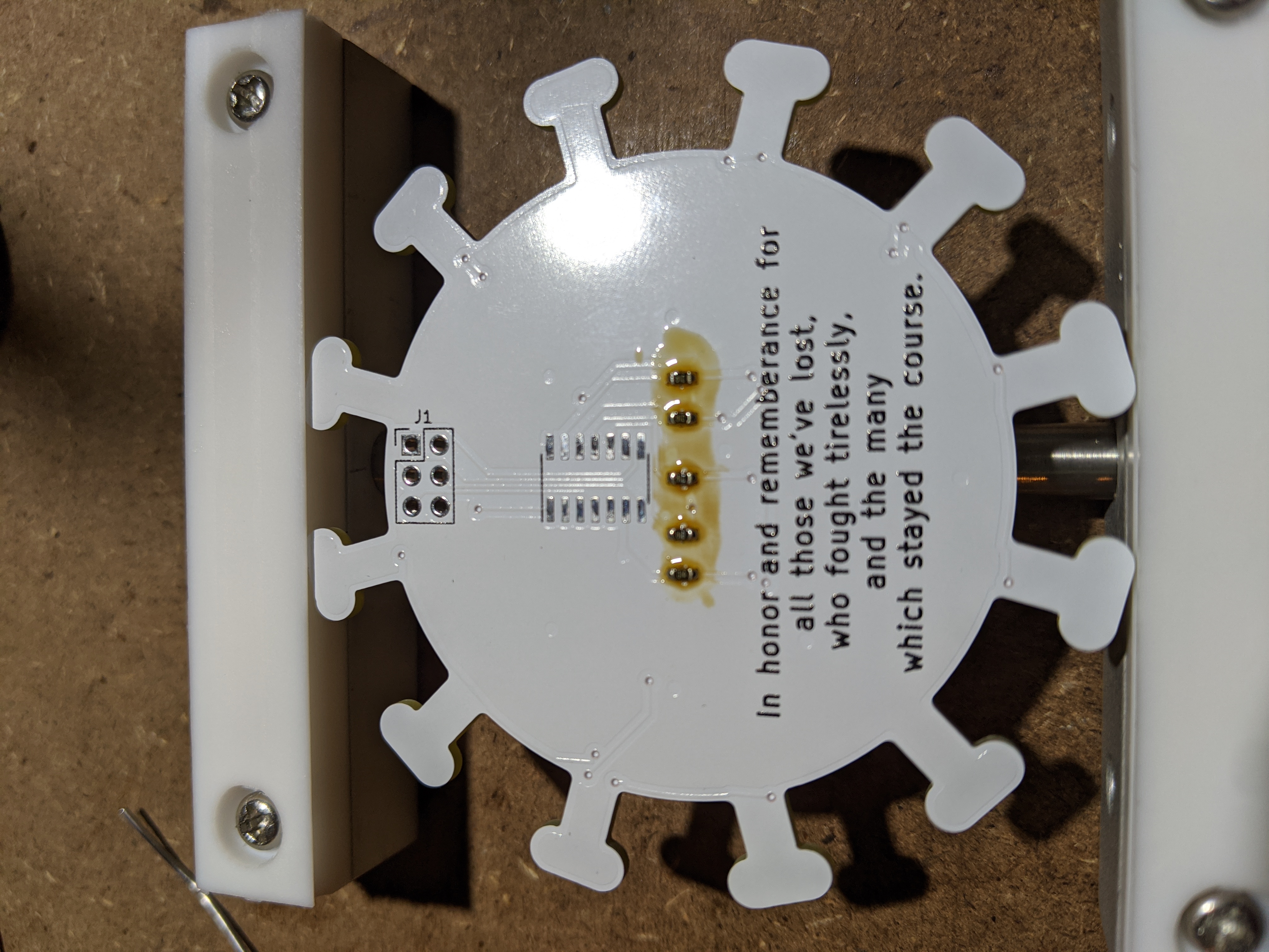
Step 1 (Resistors): There are five resistors that can be tricky to solder down on the back of the board. Flux is your friend. Embrace your friend. Get those five appropriately distanced resistors soldered down.
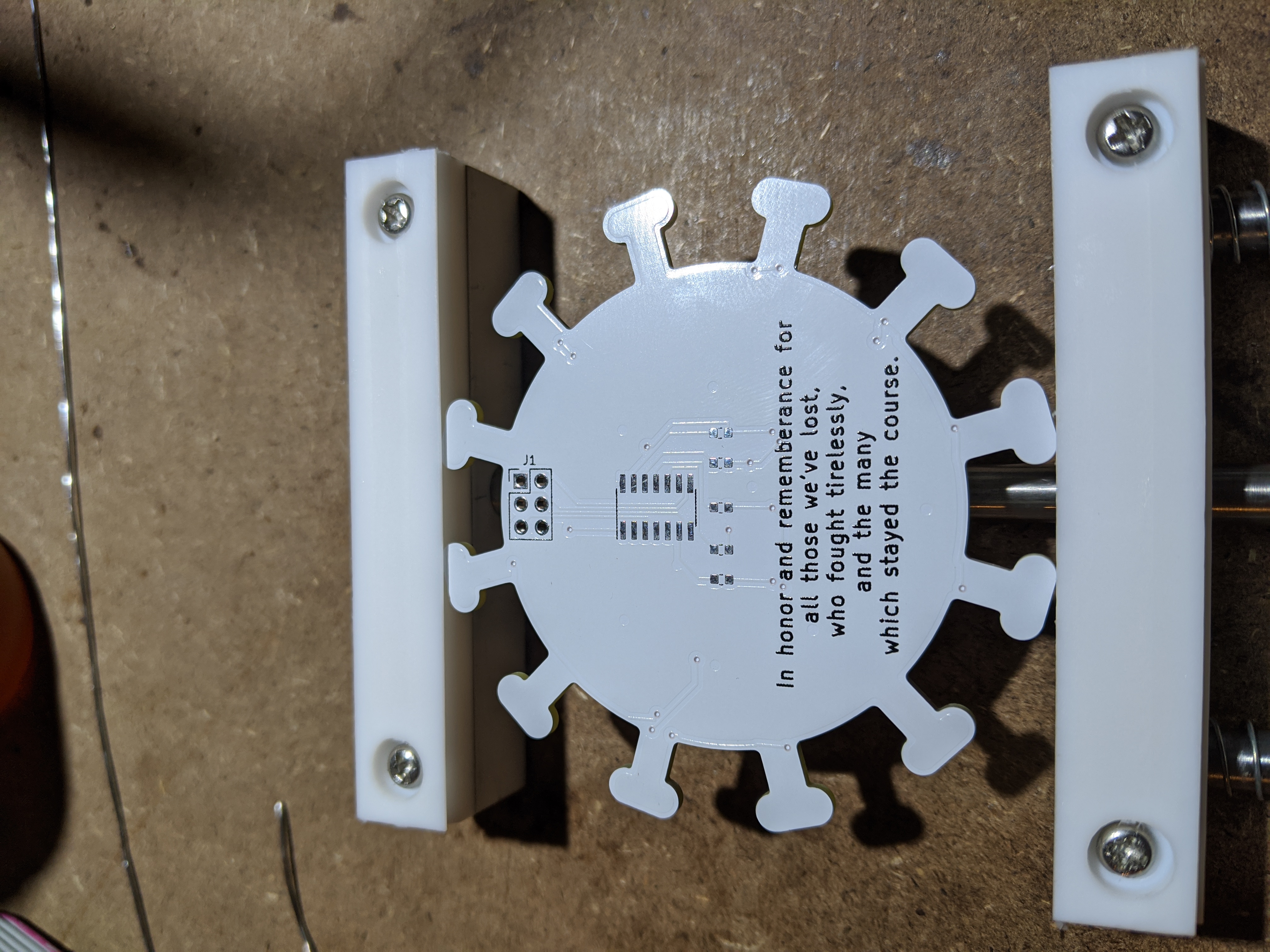
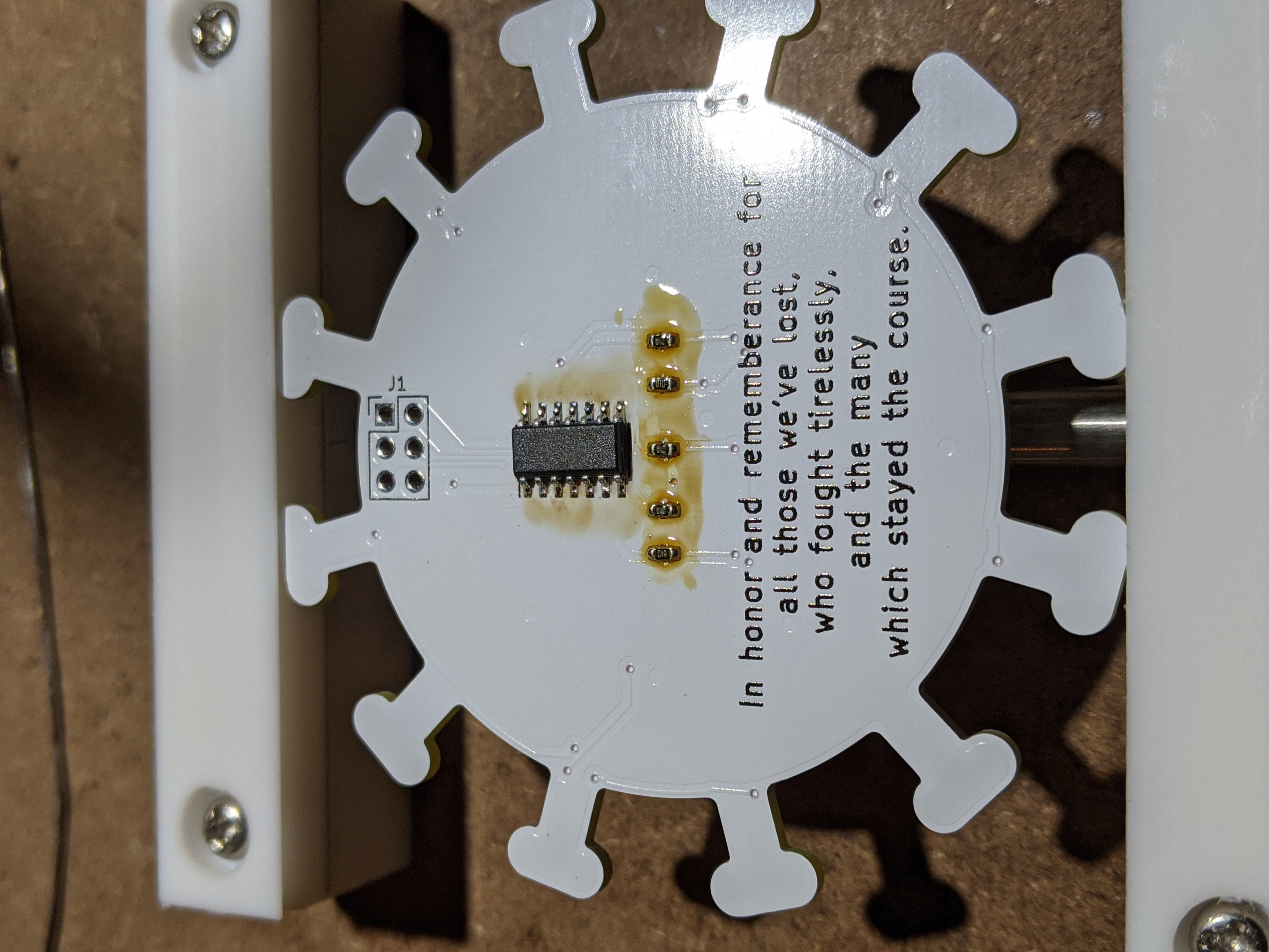
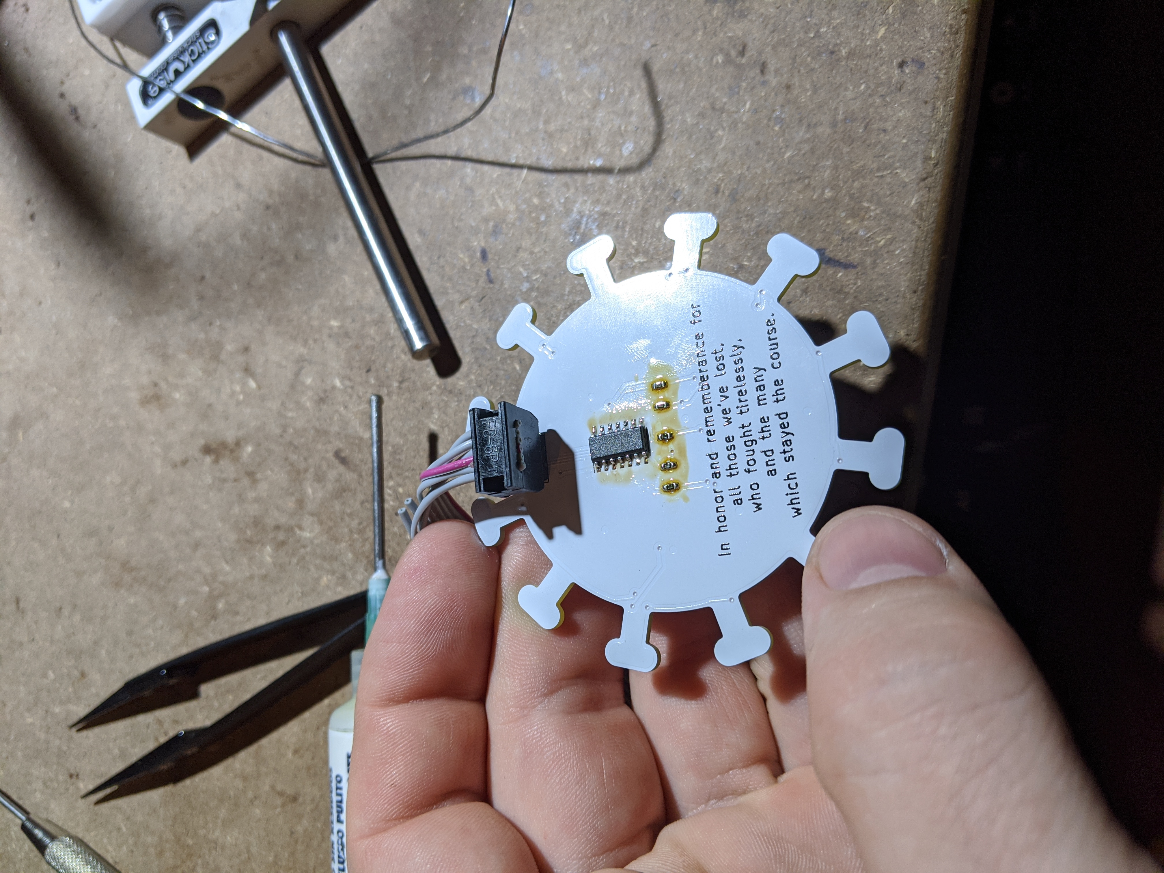
Step 2 (Solder the ATMEL): Simply put, solder on the ATMEL! The tiny dot goes up and the to the left, well, up. Towards those headers. Use a bright light.
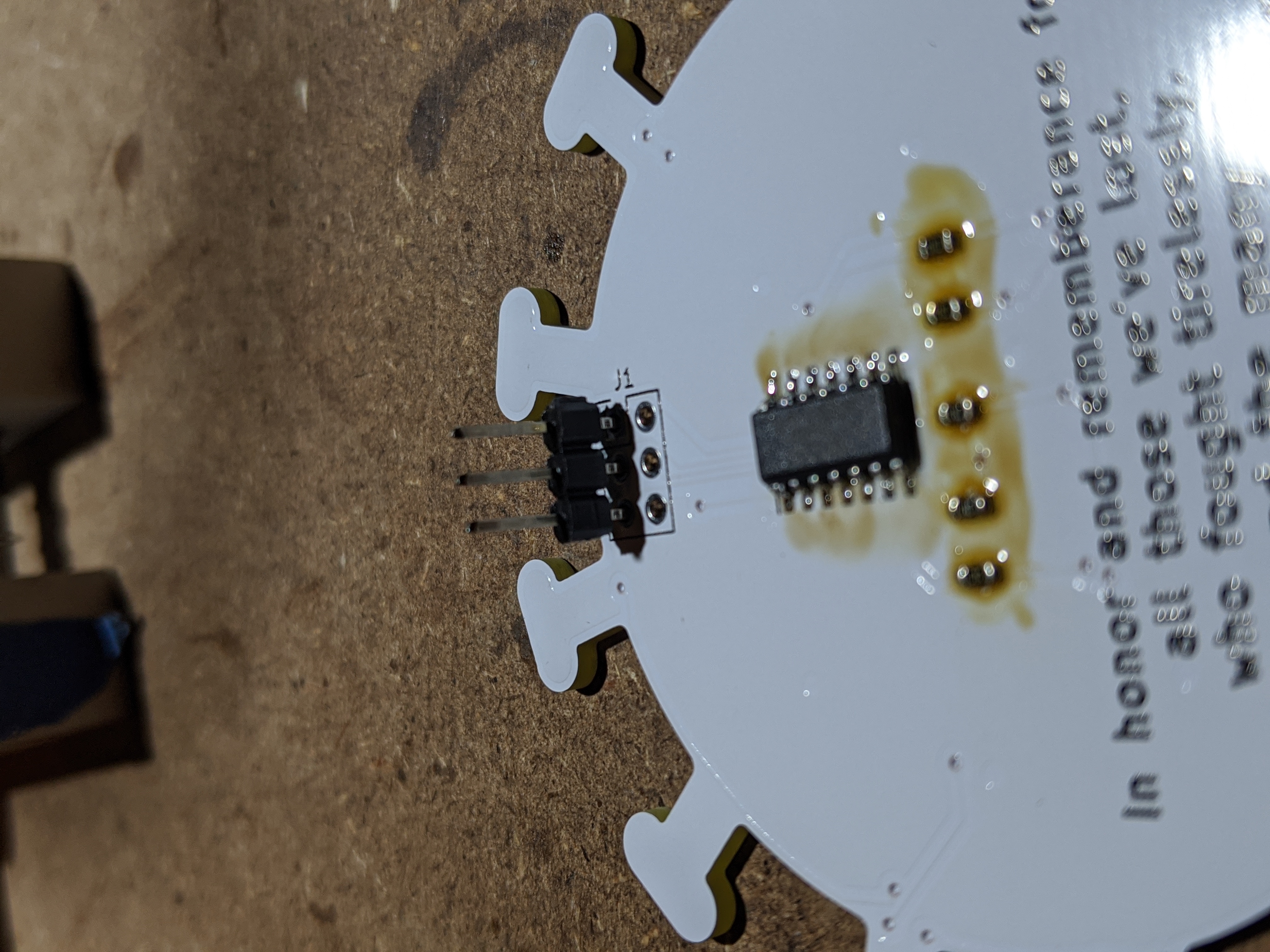
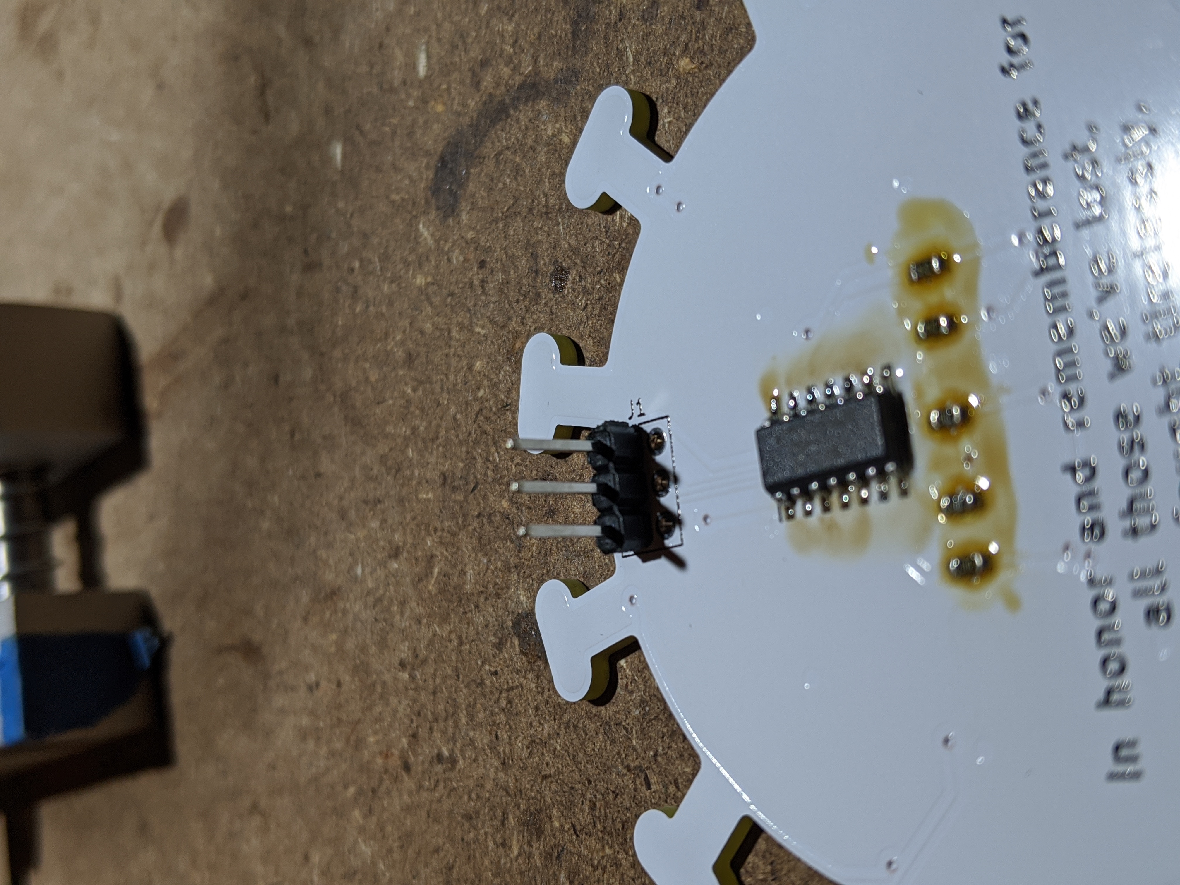
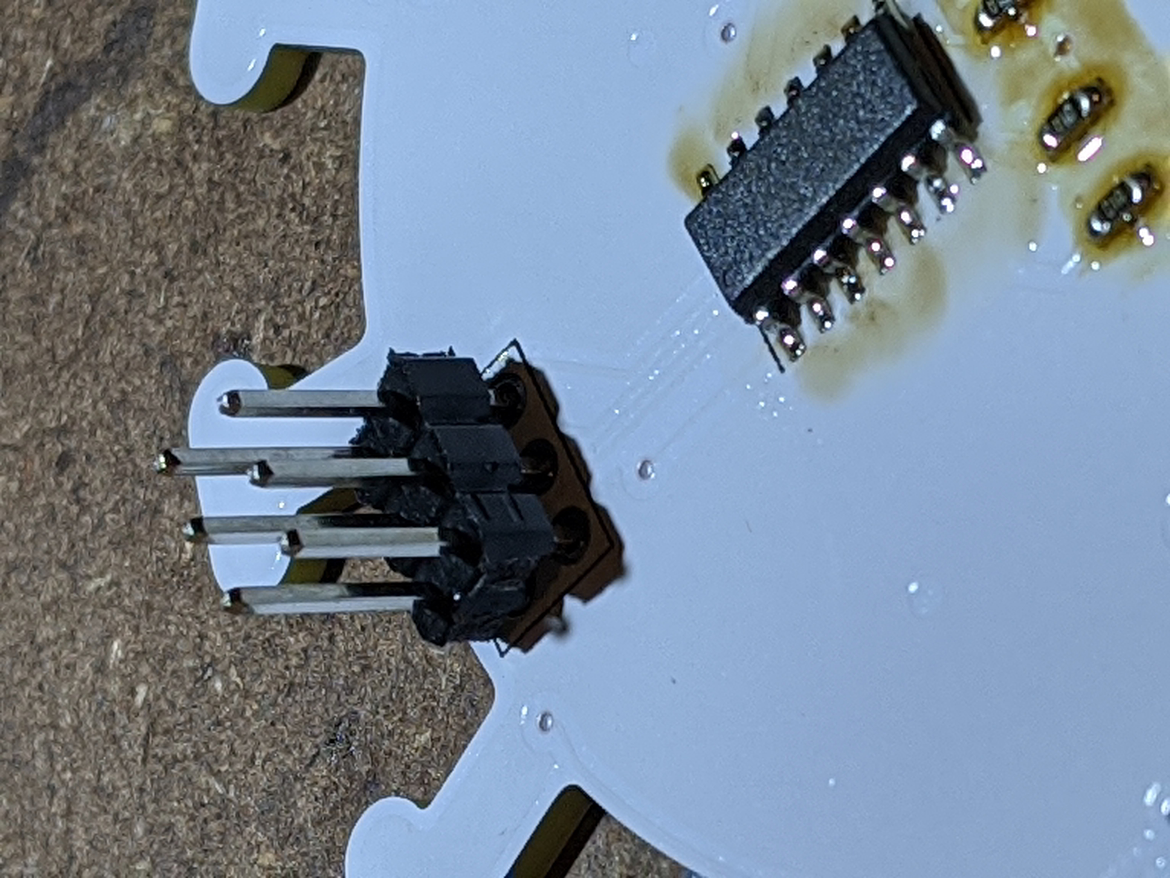
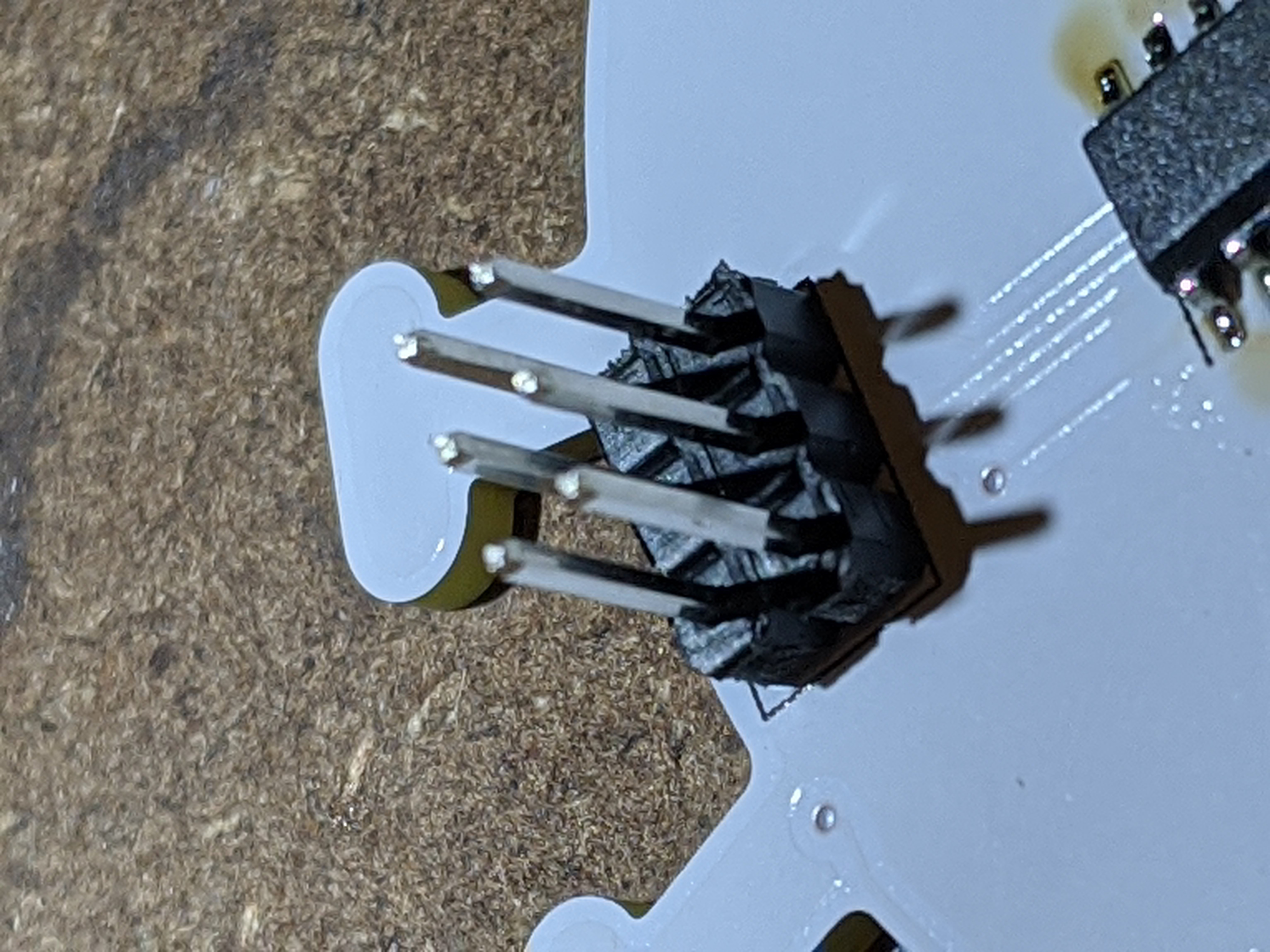
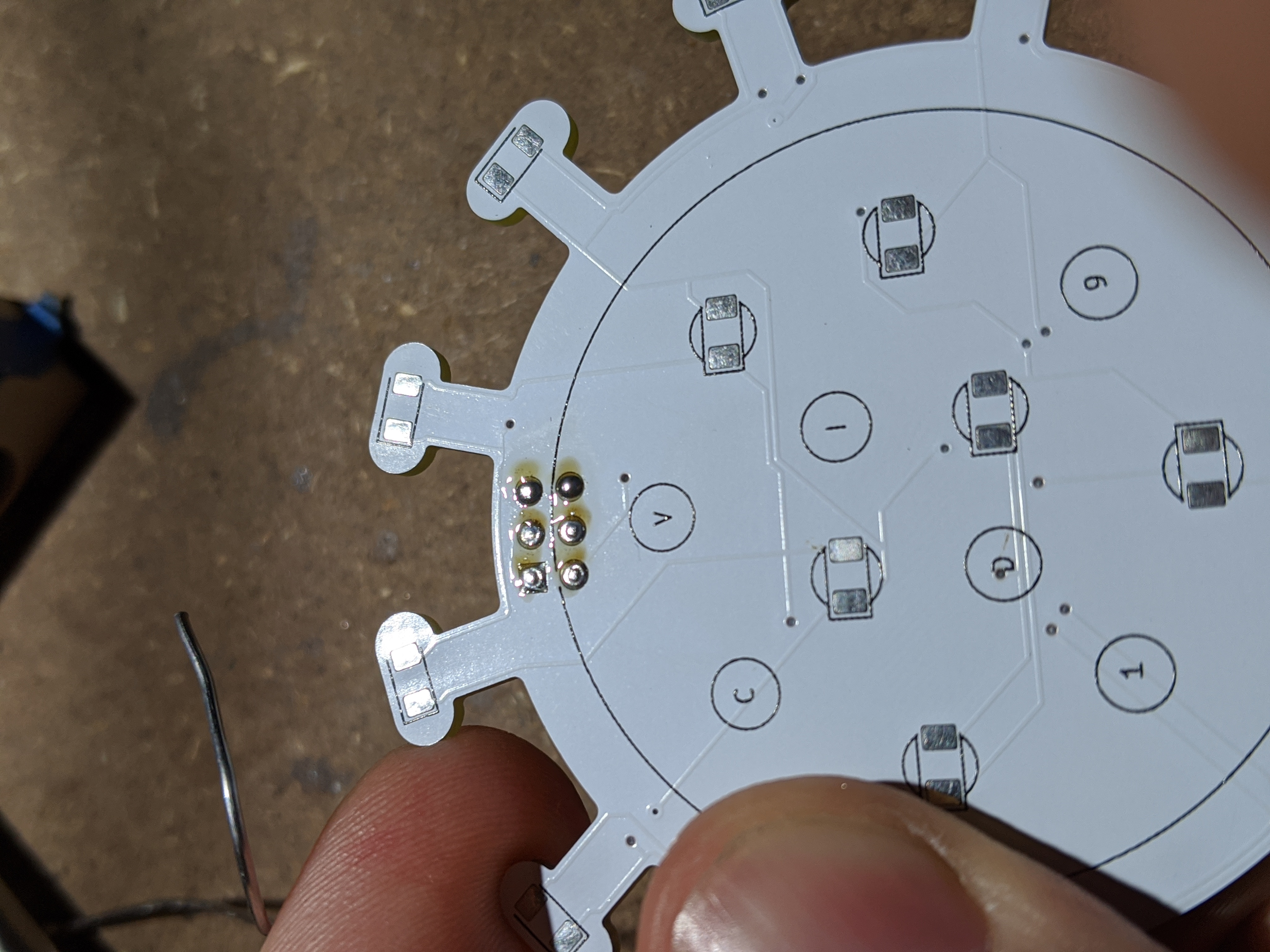
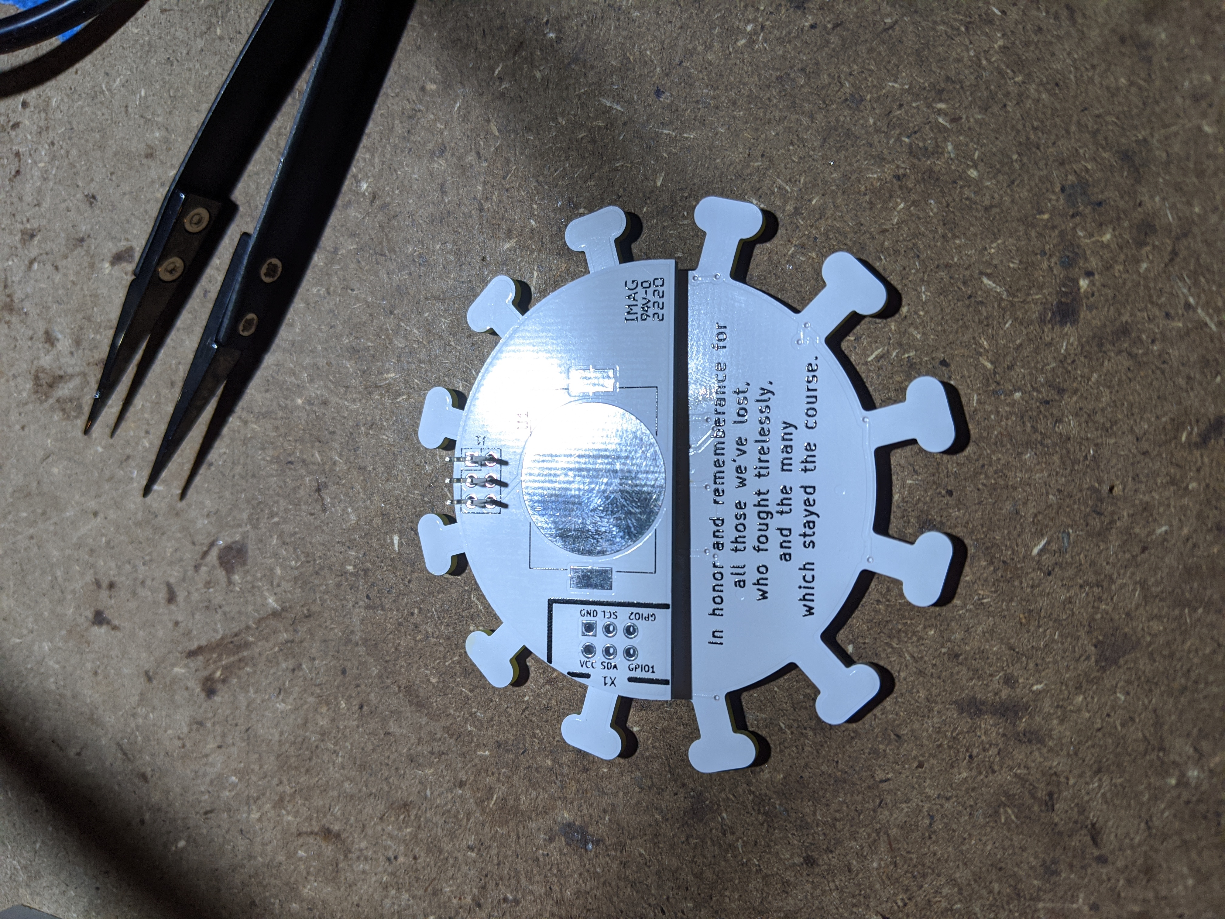
Step 3 (Solder the Programming Headers): For this part, take the board out of the grips so it lays flat on a surface. Place one of the headers into the PCB. Notice now it leans? Cool. Take your thumbs and press down on the black insulators until it is flush with the PCB and the pins stay up. Do the same thing for the second row, and then solder. This will result in a FLAT solder bead on the front facing PCB. Checkout the pics for a visual.
Step 4 (Programming): Time to plug in the AVR programmer, drop a boot loader, and upload the code using a programmer. You can get the code from here. This is Arduino code, so make sure you have the Arduino IDE installded and the ATTINY extensions as well. I first upload the Optiboot bootloader and then upload the code using the programmer.
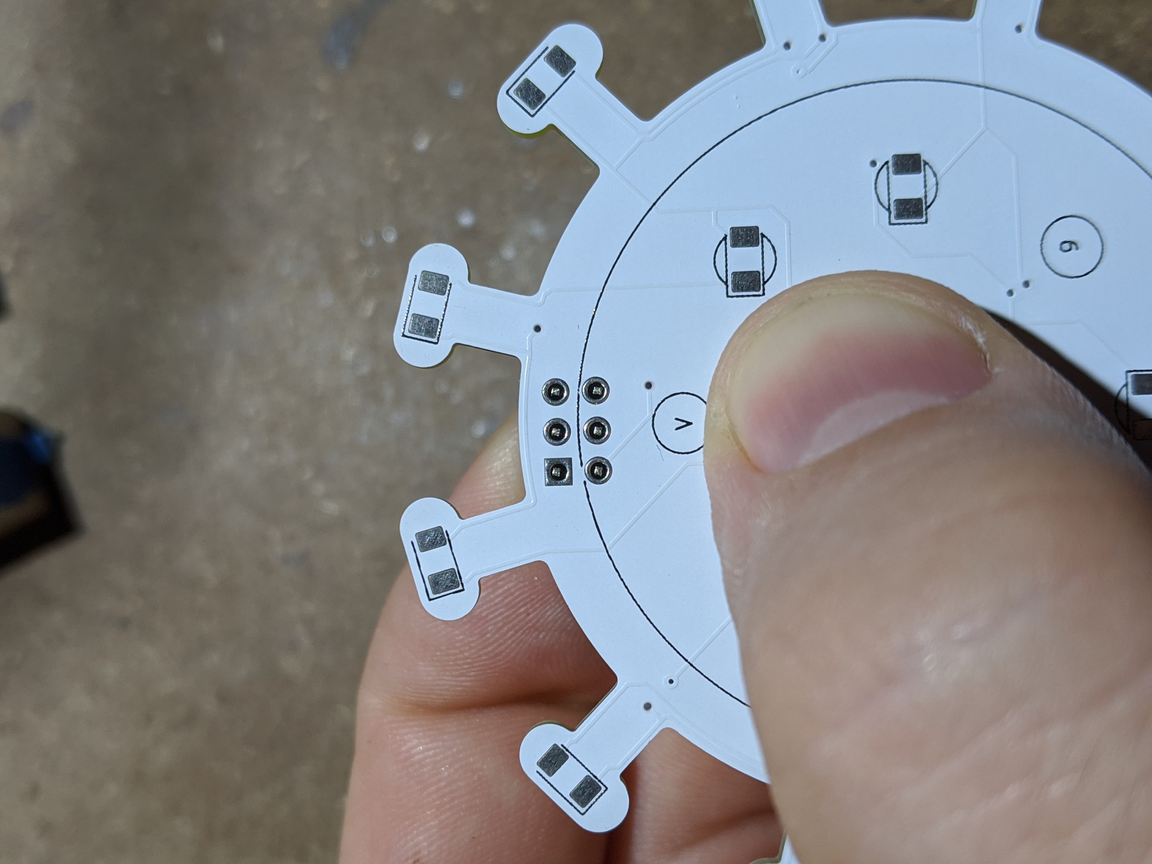
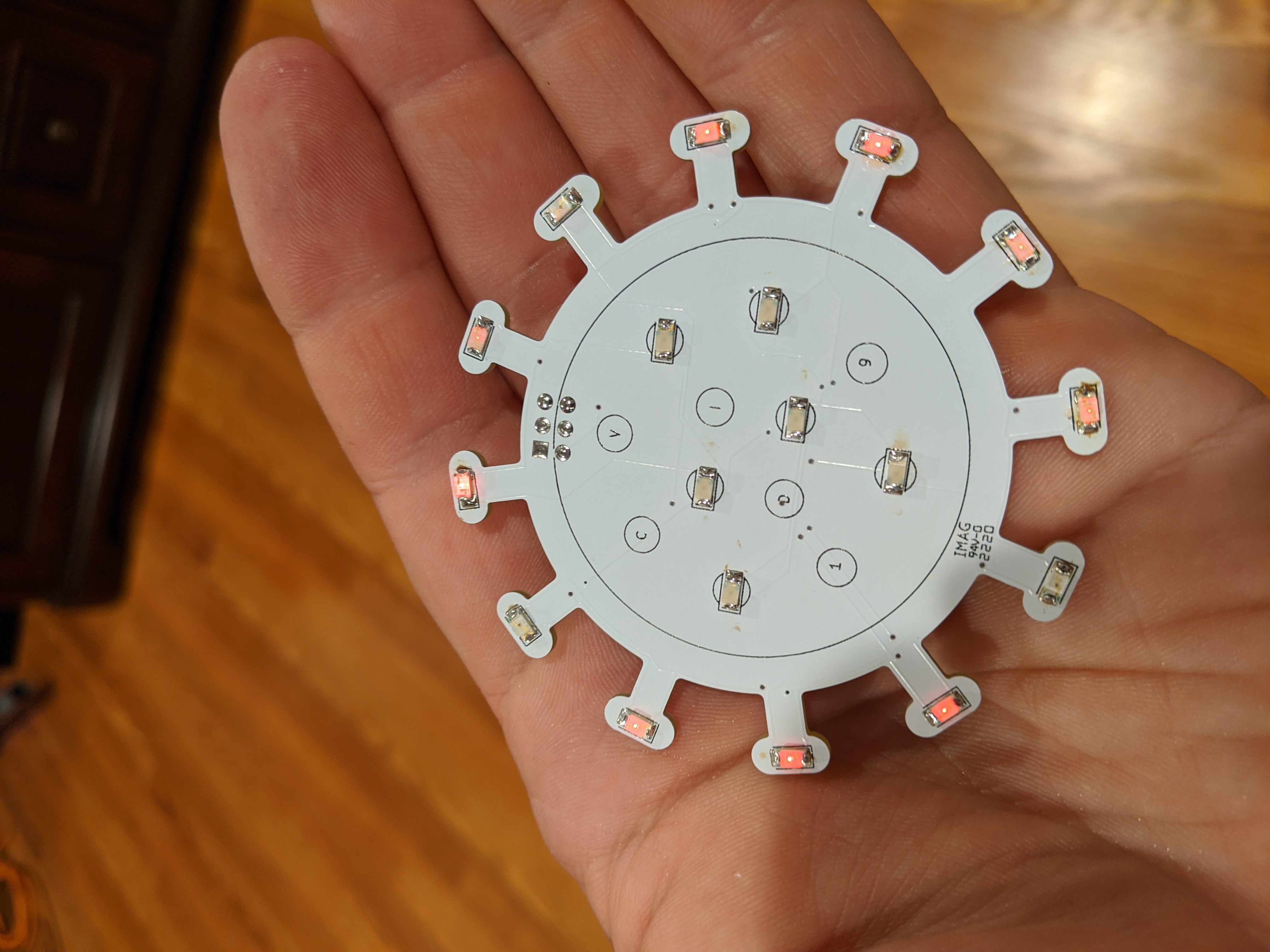
Step 6 (Green LEDs): Using flux, solder down the 6 green LEDs. It may be hard to see, but the green side on the top, which marks polarity, goes to the OPENING side of the PCB’s layout. There is ONE LED that isn’t oriented the same way.
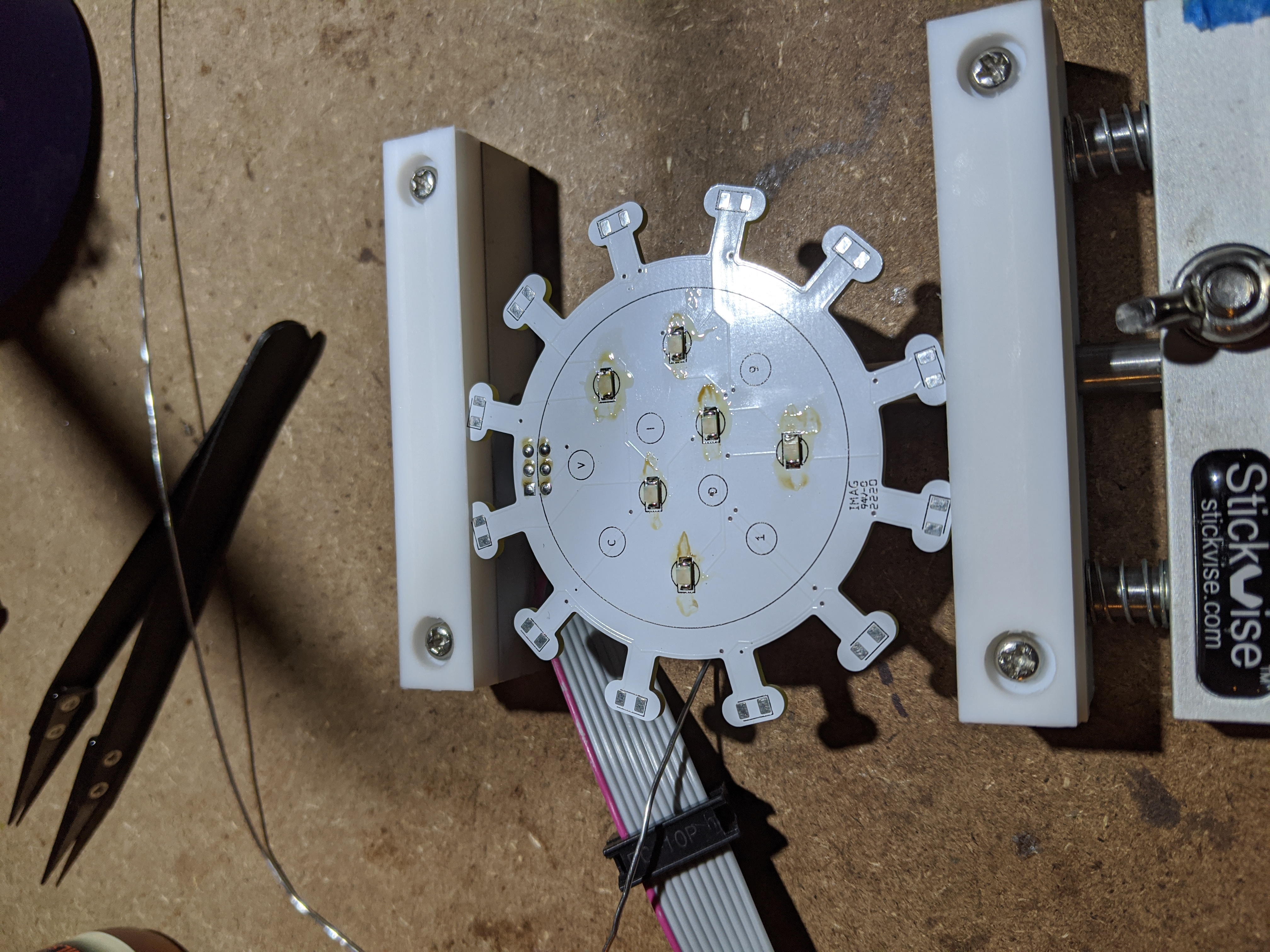
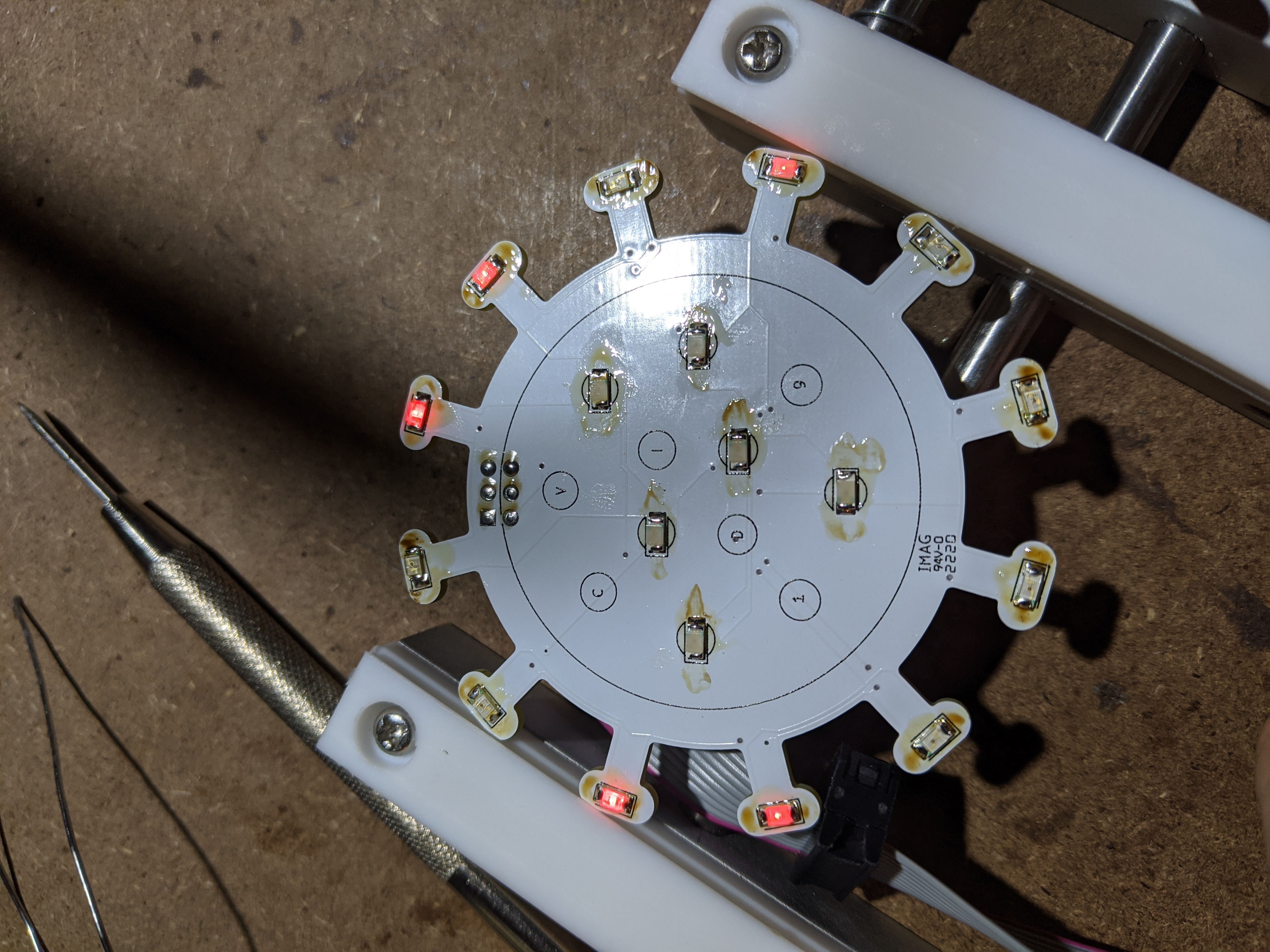
Step 7 (Red LEDs): Much like the green LEDs, same thing for the Reds. They’re all oriented the same way.
Step 8 (SAO Daughter board NOTE): Now, slide on the SAO daughter board. I like to solder down the two far extreme pins making sure the board is level-ish. Solder it down.
This kit doesn’t have the recent SAO actual header, because weird reasons. Firstly, there won’t be any cons for the most part of 2020. Secondly, I can’t find the part. Fun, right? Well, if you run into me at a con in 2021, I should have the right part and a way to solder on the SAO header in a fun and productive way. The only pins that are passed through are ground and VIN.
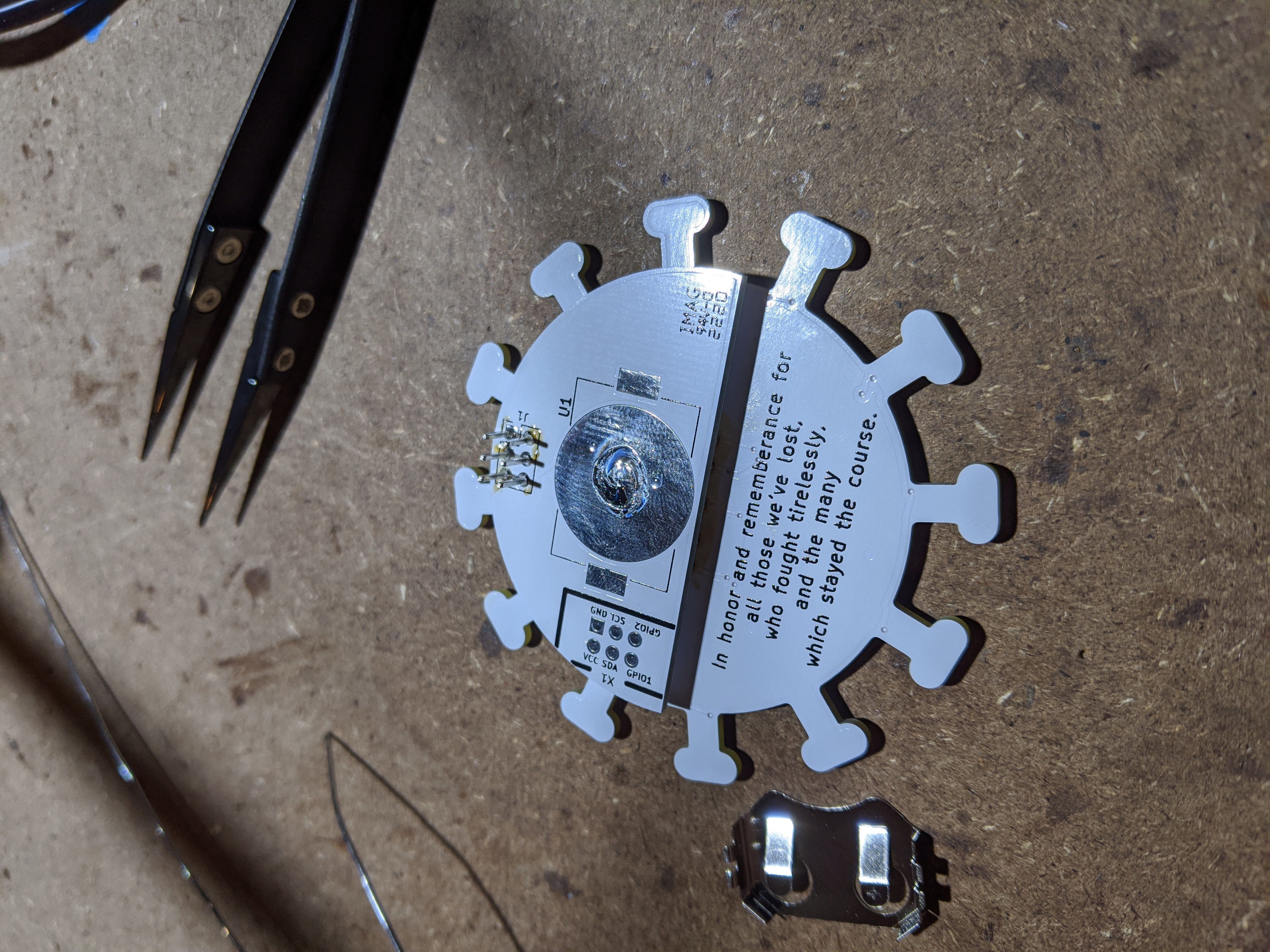
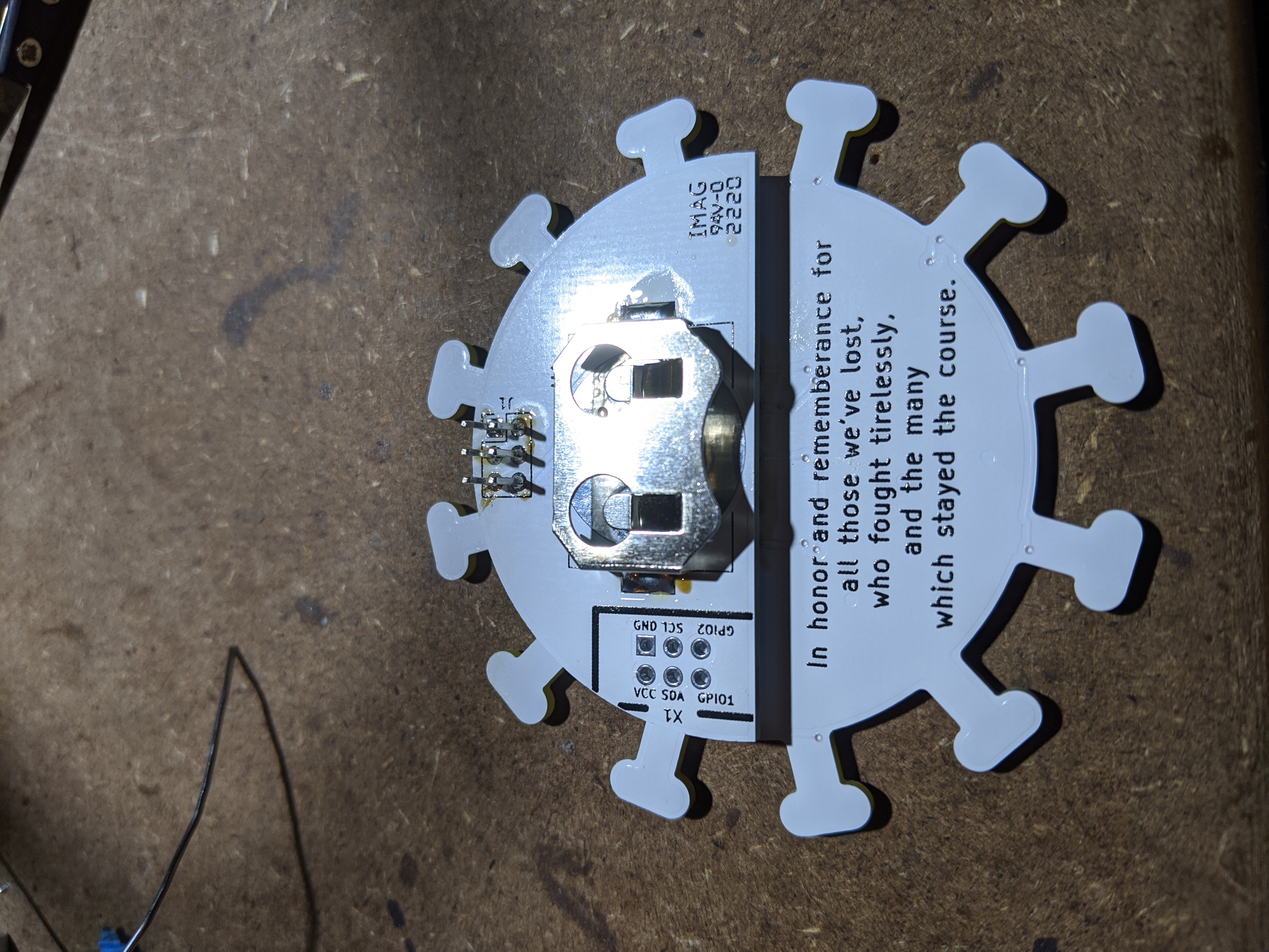
In complement of the SAO header, I included a 3.3v battery holder. If you’re inclined, glue on a pin holder anywhere onto the board and wear it on its own. For the battery pad, I placed a little bit of solder to help apply pressure on the battery.

Step 9 (Cleanup): I used a small towel and rubbing alcohol (irony) to clean up the whole board to remove all residue and flux friends. Thank you for your support!
Feel free to contact me on twitter (@dntlookbehindu) or email (russell@handorf.com) if you have any questions. This is a living document after all. Thank you!
|